Replacing an IGBT module is a controlled engineering change, not a catalog swap. Even when two modules share the same collector-emitter voltage, current class, and housing, they may differ in topology, terminal functions, conduction and switching losses, gate-drive needs, diode behavior, thermal response, insulation, or protection limits.
Start with the failed or unavailable original module. Confirm its full orderable part number and circuit, identify why it needs replacement, and compare the original and candidate datasheets under equivalent test conditions. Record the result as Pass, Hold for evidence, or Reject.
If the project is still choosing a module for a new motor-drive design, use NTCHIP's guide to choosing an IGBT module for industrial motor drives. The focus here is a failed, unavailable, or obsolete part: how engineering, procurement, quality, and maintenance teams review a replacement and prepare the RFQ evidence.
IGBT modules operate in equipment with hazardous voltage and stored energy. Only personnel qualified for the converter should perform physical installation and commissioning, following the equipment manufacturer's service procedure and applicable safety rules. Confirm availability, pricing, and lead time through RFQ.
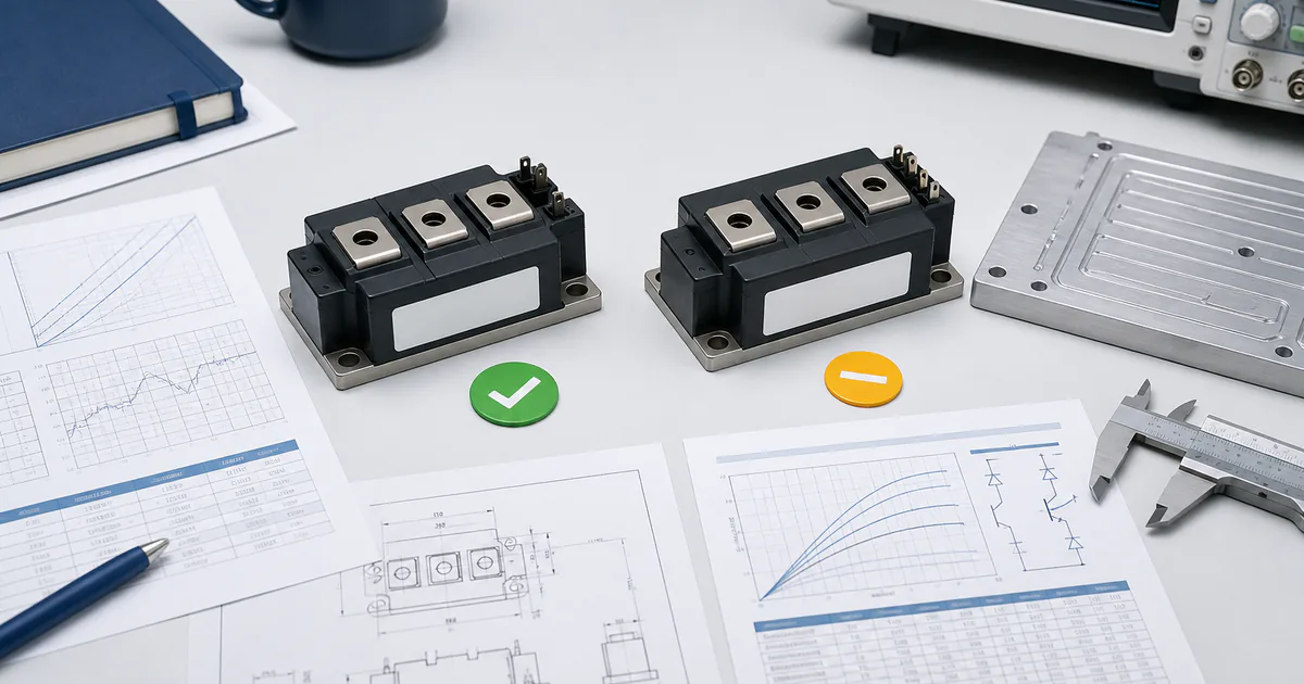
A defensible comparison keeps module identity, datasheet conditions, physical interfaces, and test evidence in one record.
Quick answer: compare the exact modules before approving a replacement
Do not approve an IGBT module replacement from voltage, current, or package name alone. This checklist covers selection, qualification, and release evidence; it is not a module-removal procedure. First verify the original module's full part number and internal circuit. Then screen for hard-stop mismatches, recalculate the electrical and thermal behavior, and validate the candidate in the actual converter under an approved test plan. Qualified personnel must follow the equipment service manual for physical work.
| Replacement path | Minimum review | Approval level |
|---|
| Exact same orderable part | Confirm manufacturer, full part number and suffixes, applicable datasheet, equipment revision, condition, and lifecycle. Correct the original failure cause and follow the current assembly procedure. | Maintenance, engineering, and quality controls defined for the equipment |
| Manufacturer-documented successor | Read the succession or cross-reference notice, then compare every relevant datasheet table, graph, note, circuit diagram, and package drawing. Record all differences. | Engineering change and validation as required by the buyer's process |
| Cross-manufacturer alternative | Treat it as a new candidate. Compare topology, terminals, ratings, losses, diode, gate drive, protection, NTC, thermal path, insulation, mechanics, lifecycle, and documentation. | Full application-specific engineering and quality approval |
Use three gates:
Must match: internal topology, every power and control terminal, package interfaces, mounting and cooling constraints, and required insulation must fit the equipment. A mismatch here normally stops the review.
Must be recalculated: conduction and switching losses, diode recovery, junction temperatures, gate-driver power, transient margin, dead time, and short-circuit protection timing depend on the candidate's data and the real circuit.
Must be tested: the corrected converter, installed module, driver, protection, cooling, switching waveforms, temperatures, and fault response need a controlled validation plan before release.
Safety boundary: An IGBT module sits behind hazardous DC-link voltage and stored capacitor energy. Only qualified and authorized personnel should open, install, test, or commission the equipment. Use the equipment maker's energy-control, discharge, measurement, ESD, and service procedures; an extinguished indicator is not proof of zero voltage.
A cross-reference can shorten the list, but it cannot approve the substitute. Nor does a higher voltage or current label settle the decision; the proposed module may have different losses, gate charge, diode behavior, or package construction.
Start with the failure, not the replacement part
A new module can fail for the same reason as the original. Before comparing candidates, preserve the evidence and determine which system conditions need investigation. A damaged IGBT does not, by itself, identify the initiating fault.
| Evidence to preserve | What it may help the qualified team review |
|---|
| Full module label, all suffixes, date/lot markings, and photographs | Exact identity, manufacturing variation, prior repair, and sourcing history |
| Fault log, alarm history, and operating state at failure | Load, protection, temperature, and sequence context |
| Failed position and damage pattern | Whether the event affected one switch, one phase, a diode path, terminals, or more than one module |
| Gate-driver board, connections, and protection settings | Missing drive, false turn-on, insufficient isolation, or delayed fault response |
| DC-link, snubber, busbar, and connection condition | Overshoot, excess loop inductance, loose joints, or abnormal current paths |
| Heatsink, thermal interface, fasteners, fan or liquid-cooling condition | Poor heat transfer, uneven mounting, blocked airflow, or cooling-system failure |
| Load, cable, motor, transformer, or downstream inspection results | Short circuit, ground fault, overload, or abnormal commutation outside the module |
| Contamination, corrosion, moisture, and enclosure condition | Insulation or environmental stress |
The review should cover the driver and power stage together. An open gate connection, incorrect dead time, failed desaturation circuit, degraded capacitor, damaged snubber, poor thermal contact, or downstream fault can contribute to repeat failure even when the module's headline ratings appear suitable.
Do not clean away damage, discard the label, or change protection settings before the responsible team records the evidence. If the cause remains unknown, mark it as an open risk and do not move directly to full-power operation. Proceed to validation only after the initiating fault has been corrected or controlled.
Identify the original module and its circuit
Use the full orderable part number from the module label, purchasing record, equipment BOM, and manufacturer document. Family names, abbreviated markings, photographs, and distributor descriptions are not enough.
| Identity field | Evidence to retain | Stop condition |
|---|
| Manufacturer and full MPN | Label photographs, BOM, invoice, and service record | Manufacturer or MPN cannot be confirmed |
| Suffixes and option codes | Exact label text and manufacturer ordering table | A suffix meaning is unknown |
| Datasheet revision | Saved manufacturer PDF, revision, source, and review date | Only an undated summary is available |
| Equipment revision | Model, serial range, PCB revision, and applicable service bulletin | The circuit revision cannot be established |
| Lifecycle status | Current manufacturer record, PCN, PDN, or EOL notice where applicable | The sourcing path conflicts with the equipment change process |
| Internal circuit | Manufacturer equivalent-circuit diagram and equipment schematic | The topology is unknown or different |
| Mechanical outline | Dimensioned manufacturer drawing and equipment interface record | Fit is inferred only from appearance |
Trace every connection. Confirm collector and emitter power terminals, phase or DC terminals, gate pins, auxiliary or Kelvin emitters, thermistor pins, current-sense outputs, brake elements, and any integrated driver or protection functions. A half-bridge module, chopper, six-pack, seven-pack, intelligent power module (IPM), and single-switch module are not interchangeable categories.
If the original is an IPM, extend the comparison beyond the external gate-loop checks used for a conventional power module. Match its control-supply requirements, logic-input thresholds and timing, fault output, reset behavior, built-in protection, and temperature or current-sense interfaces. The equipment controller may depend on those functions even when the power-terminal layout appears unchanged.
The housing can mislead. Two modules may share an outline while assigning different functions to auxiliary pins or using different internal connections. Treat an unknown topology, unverified terminal, or ambiguous suffix as a hold point.
If obsolescence triggered the replacement, first check the lifecycle status for the exact electronic component. A family-level status or a distributor's label does not establish the current status of every suffix. Record the source and review date, then decide whether the RFQ is exact-part only, may accept a manufacturer-documented successor, or may return candidates for engineering review.
Use three decision gates: must match, must recalculate, must test
Classify each parameter before deciding on the module. A favorable headline rating should not hide an interface mismatch or an unverified system change.
| Decision gate | Typical checks | Evidence | Decision rule |
|---|
| Must match | Functional topology, every terminal, package interface, cooling interface, and required insulation role | Exact datasheets, circuit diagrams, package drawings, and equipment records | Reject when a required interface is different; hold when it is unknown |
| Must recalculate | Conduction and switching loss, diode loss, junction temperature, gate-driver load, transient margin, dead time, and protection timing | Normalized datasheet data, measured or specified application conditions, and engineering calculations | Hold until the responsible engineer documents acceptable margin |
| Must test | Assembly quality, protection response, switching waveforms, overshoot, oscillation, current, and temperatures | Approved validation plan and recorded results | Release only through the buyer's equipment-change process |
A parameter can cross more than one gate. Gate resistance changes driver current and switching loss, then requires waveform validation. Insulation must satisfy the system requirement, while the datasheet's proof-voltage entry still needs interpretation against its test conditions.
Copy this datasheet comparison worksheet
Record both values, the conditions behind them, the source revision, the responsible owner, and a verdict. Use Pass, Hold, or Reject; do not let a blank cell become an assumed pass.
| Check area | Datasheet symbol or drawing | Original module | Candidate module | Conditions or evidence to compare | Owner | Verdict |
|---|
| Internal circuit and topology | Equivalent-circuit diagram | | | Switch/diode arrangement, brake or rectifier elements, integrated drive/protection | Engineering | |
| Power and control terminals | Terminal map | | | Every terminal function, polarity, auxiliary emitter, NTC, sense and unused pins | Engineering / service | |
| Blocking and current limits | VCES, IC, ICRM, SOA data | | | DC link, overshoot, waveform, duty, case and junction temperature | Engineering | |
| Conduction loss | VCE(sat) | | | IC, VGE, Tj, minimum/typical/maximum status | Engineering | |
| Switching loss | Eon, Eoff, timing data | | | VCC, IC, Tj, VGE, RG, stray inductance, measurement definition | Engineering | |
| Freewheeling diode | VF, trr, Qrr, Err | | | IF, VR, di/dt, Tj, RG, circuit conditions | Engineering | |
| Gate-driver demand | QG, Cies, Crss, internal RG | | | Drive voltages, switching frequency, peak current, average power, loop inductance | Engineering | |
| Protection behavior | RBSOA, SCSOA, tSC | | | Bus voltage, Tj, VGE, RG, detection and turn-off delays | Engineering | |
| Temperature sensing | NTC R25/B curve and pins | | | Sensor location, tolerance, sensing current, thresholds, insulation | Controls / engineering | |
| Thermal path | Rth and Zth for IGBT and diode | | | Loss model, pulse duration, case reference, TIM, heatsink and coolant/airflow | Thermal / engineering | |
| Cyclic lifetime | Power-cycling and thermal-cycling data | | | Mission profile, ΔTj, mean and peak Tj, on-time, dwell, cycle count, package technology | Reliability / engineering | |
| Mechanical interface | Dimensioned drawing | | | Footprint, height, holes, terminals, busbar, fasteners, forces and access | Mechanical / service | |
| Insulation | Viso, creepage, clearance, CTI | | | Test waveform and duration, working voltage, pollution degree and altitude | Safety / engineering | |
| Lifecycle and documentation | Status, PCN/PDN, document list | | | Exact orderable part, revision, source, review date and approval path | Procurement / quality | |
The worksheet is a comparison record, not a substitute for calculations, testing, or approval. A product search or cross-reference can populate the candidate column, but it cannot fill in the verdict. NTCHIP's guide to finding an electronic component equivalent explains the same distinction across other component types.
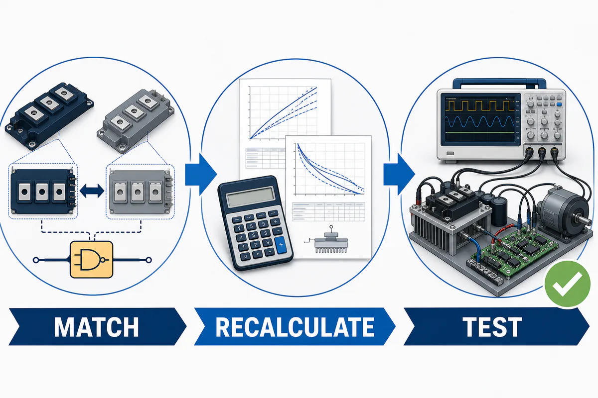
A candidate advances only after hard-stop interfaces match, affected behavior is recalculated, and the system is validated.
Compare electrical ratings, losses, and the freewheeling diode
Start with voltage, current, temperature, and safe-operating-area limits, but read the conditions attached to each value. VCES is a device limit, not the acceptable DC-link target. The application still needs margin for supply tolerance, regeneration, switching overshoot, fault conditions, and temperature.
Collector-current ratings also depend on defined thermal conditions. A higher IC does not prove that the candidate can carry more current with the existing heatsink, switching frequency, and duty cycle. Compare continuous and pulse-current limits, the applicable reverse-bias safe operating area (RBSOA), operating junction-temperature range, and any restrictions on repetitive use.
Keep four evidence classes separate:
| Datasheet evidence | How to use it |
|---|
| Absolute maximum rating | A stress boundary that normal operation should not reach |
| Specified minimum or maximum | A limit that applies only with its stated conditions and notes |
| Typical table value | An engineering estimate, not a guaranteed worst-case value |
| Typical curve | Trend data that requires interpretation, interpolation, and application margin |
The onsemi guide to reading IGBT datasheets explains how maximum ratings and electrical characteristics are defined. Apply those definitions to the original and candidate documents; do not move a typical value into a worst-case column.
Compare conduction and switching loss under equivalent conditions
For conduction loss, compare VCE(sat) at the intended collector current, gate voltage, and junction temperature. Use a specified maximum when the design needs a guaranteed limit. A lower typical value measured at another current or temperature does not establish a lower worst-case loss.
For switching loss, record the conditions behind Eon, Eoff, delay, rise, and fall data:
switching voltage and collector current;
junction temperature;
turn-on and turn-off gate voltages;
external gate resistance and driver conditions;
test circuit, stray inductance, and measurement definition;
whether the value is typical or specified as a limit.
Energy values measured under different conditions are not directly comparable. Manufacturers may also define the contribution of diode recovery or other intervals differently. Recalculate the candidate's loss over the converter's real current waveform and switching cycle.
Infineon's AN 2011-05 on industrial IGBT module technical information connects switching, diode, thermal, NTC, insulation, and short-circuit parameters. It is an interpretation guide; the exact module datasheet and its current revision still control the comparison.
Review the freewheeling diode as a separate power device
Compare the diode's continuous and peak current, forward voltage, reverse-recovery time, charge or energy, peak recovery current, thermal data, and reverse-recovery safe operating area (RRSOA) where specified. Keep the test current, reverse voltage, di/dt, junction temperature, and gate-resistance conditions with each value.
A candidate with acceptable IGBT ratings can still increase total converter loss or overshoot if its diode behaves differently during commutation. Calculate IGBT conduction loss, IGBT switching loss, diode conduction loss, and diode recovery loss as separate terms before assessing the thermal path.
A higher voltage or current class brings a different data set, not an automatic upgrade. It may change VCE(sat), gate charge, switching energy, diode recovery, package construction, and the protection margin that the existing converter depends on.
Revalidate the gate driver, protection, and NTC circuit
Do not reuse the original driver settings by default. Compare the candidate's recommended turn-on and turn-off gate voltages, maximum VGES, threshold-voltage range, total gate charge, capacitances, internal gate resistance, and any permitted range for external gate resistance.
VGE(th) is not the normal drive voltage. It identifies the point at which the device begins to conduct a small stated test current. It does not show that the IGBT is fully enhanced at the converter's load current.
Check the complete gate loop
| Check | Why the replacement can change it |
|---|
| Gate charge and charge curve | Sets driver peak current, switching transition, and average driver-power demand with switching frequency |
| Input and reverse-transfer capacitance | Affects transition behavior and susceptibility to Miller-induced turn-on |
| Internal and external gate resistance | Changes di/dt, dv/dt, switching loss, overshoot, diode recovery, oscillation, and EMI |
| Turn-on and turn-off paths | Separate resistors, diodes, negative bias, active clamping, or a Miller clamp may need a fresh review |
| Gate-loop inductance and auxiliary emitter | Layout and Kelvin-emitter use affect the voltage seen by the die during rapid current change |
| Driver isolation and common-mode behavior | A different switching edge can expose isolation or CMTI limits in the existing driver |
Do not keep or change the original gate resistor by rule of thumb. Start with the candidate manufacturer's data, include driver output resistance and loop parasitics, then verify switching loss, overshoot, oscillation, and EMI in the actual converter.
Recheck fault detection and turn-off
Review the complete protection path:
desaturation or current-sense threshold and tolerance;
blanking, propagation, and logic delays;
soft turn-off, clamping, and peak collector-emitter voltage during a fault;
driver undervoltage lockout and isolation behavior;
dead time and false-turn-on susceptibility;
the candidate's RBSOA, SCSOA, and short-circuit data under their stated conditions.
Do not treat a published short-circuit withstand time as a universal permissible delay. Compare the complete fault condition: bus voltage, gate voltage, junction temperature, gate resistance, SCSOA, total detection and turn-off delay, fault current or energy where documented, and test circuit. The engineering review must show that the protection path stays within the candidate's stated limits with the required application margin.
Mitsubishi Electric's T/T1 Series application note discusses gate resistance, drive power, dead time, short-circuit protection, thermistor use, mounting, and loss calculation. Its numeric guidance applies to the covered families and stated conditions; it is not a universal setting for unrelated modules.
Confirm what the NTC actually measures
If the module contains an NTC thermistor, confirm its pins, reference resistance, B value or full resistance-temperature curve, tolerance, sensing current, allowable dissipation, and insulation arrangement. Recalculate the sensing circuit and alarm or shutdown thresholds.
An internal NTC usually tracks a substrate or case-related location with thermal delay. It does not measure the instantaneous IGBT junction temperature and should not be treated as short-circuit protection. Keep the junction-temperature calculation and the NTC protection function as separate checks.
Recalculate thermal, mechanical, and insulation fit
Thermal approval requires a new loss model and a complete heat-path review. Compare IGBT and diode data separately. Confirm whether each value is junction-to-case, case-to-heatsink, junction-to-heatsink, or another reference, and use transient thermal impedance for pulsed or time-dependent loading.
Rth describes steady thermal behavior for its stated path; Zth describes the time response. Use either only with the candidate's loss, pulse duration, case-temperature reference point, thermal interface, heatsink or coolant conditions, ambient temperature, and tolerances.
Matching the calculated peak junction temperature is still not evidence of equal cyclic lifetime. For equipment exposed to repeated load or ambient cycles, compare the mission profile with applicable manufacturer power-cycling and thermal-cycling data. Record temperature swing (ΔTj), mean and peak junction temperature, on-time, dwell time, cycle count, cooling cycle, and package technology. Infineon's family-specific PrimePACK application and assembly note ties targeted lifetime calculations to the load profile. Because such models are package- and family-specific, do not carry its numeric limits into another module family without applicable manufacturer data and expert review.
Check every physical interface
| Interface | What to verify |
|---|
| Base and heatsink | Footprint, baseplate or substrate form, contact area, flatness, roughness, cleanliness, and allowable condition |
| Mounting | Hole locations, fastener type, tightening sequence, permitted torque or force, and package-specific instructions |
| Power terminals | Position, height, thread or connection type, busbar alignment, permitted terminal load, and loop inductance |
| Control interface | Pin position, pitch, height, soldered or press-fit construction, gate and auxiliary-emitter mapping, NTC and sense pins |
| Thermal interface | Approved TIM type, application method, coverage or thickness, pre-applied material, and rework restrictions |
| Assembly envelope | Module height, creepage and clearance paths, nearby parts, barriers, wiring, and service access |

Mechanical fit includes the thermal interface, mounting load, terminals, cooling path, and insulation geometry.
Use the exact module and equipment instructions for every numeric torque, surface-finish, flatness, TIM, and tightening-sequence requirement. Copying an assembly value from another family can crack the housing, distort the baseplate, overload a terminal, or increase contact thermal resistance.
Fuji Electric's current IGBT Module Application Manual library treats module selection, troubleshooting, protection, cooling, gate drive, parallel operation, and evaluation as separate tasks. A mechanical match does not close the electrical or thermal gates.
Interpret insulation data in the system context
Compare isolation test voltage together with its waveform, RMS or peak definition, frequency, duration, connection points, and referenced standard. A short-duration proof test is not automatically the continuous working voltage of the installed system.
The equipment review still needs the intended working voltage, overvoltage category where applicable, creepage, clearance, material group or comparative tracking index, pollution degree, altitude, barriers, cooling structure, and any safety or customer requirements. An internal NTC or auxiliary circuit may also have a different insulation relationship from the power terminals.
If modules operate in parallel, add another gate. Confirm the manufacturer's matching or ranking requirements, current derating, and the symmetry of the power and gate-drive paths. Equal nominal ratings do not justify mixing unmatched modules or changing only one position when the equipment procedure requires a coordinated set.
Keep the candidate on hold until the exact drawings, module instructions, system calculations, and validation plan resolve every cooling, mounting, terminal-load, insulation, and parallel-sharing question.
Assign each decision to the right owner
The replacement review crosses procurement, engineering, quality, and service. Procurement can identify supply options, but it should not approve electrical or mechanical compatibility. Assign each decision and its required evidence before the search begins.
| Decision area | Primary owner | Required evidence | Approval boundary |
|---|
| Original-part identity, quantity, and required date | Procurement | Full manufacturer part number, suffixes, photos, quantity, and equipment reference | Confirm the purchasing requirement; do not infer compatibility from a similar description |
| Lifecycle and sourcing route | Procurement with engineering input | Manufacturer notices, datasheet revisions, source documents, and candidate history | Classify the exact part, documented successor, or proposed alternative |
| Electrical and topology comparison | Power-electronics engineering | Circuit topology, voltage and current limits, loss data, diode characteristics, and safe operating area | Approve or reject the candidate for the application |
| Gate-drive and protection review | Power-electronics or controls engineering | Gate-charge data, drive voltages, resistor values, DESAT settings, dead time, and fault response | Recalculate and validate the driver and protection behavior |
| Thermal, mechanical, and insulation fit | Engineering | Loss model, thermal impedance, cooling interface, package drawing, terminal layout, and insulation data | Approve the mounting and system-level design |
| Documentation and acceptance criteria | Quality | Traceability requirements, inspection plan, change record, and nonconformance process | Define the evidence required before acceptance |
| Removal, installation, and commissioning | Qualified service or maintenance personnel | Equipment procedure, energy-control record, assembly record, and commissioning results | Perform only work authorized by the equipment procedure |
When preparing an NTCHIP RFQ, buyers should organize sourcing and documentation requirements without treating supplier input as engineering approval for a converter, drive, inverter, or power assembly. NTCHIP's quality approach can inform the documentation and inspection questions that the buyer includes in the RFQ; the requested scope still needs case-specific confirmation.
Install and commission only under the equipment procedure
Physical replacement and commissioning must be performed by qualified personnel who understand the equipment, its stored-energy hazards, and the applicable electrical-safety rules. This sourcing and datasheet checklist does not replace a high-voltage service procedure.
Before physical work begins, the responsible employer and service team should apply the equipment-specific energy-control procedure, including isolation, lockout/tagout, stored-energy control, and verified de-energization. OSHA's application of energy-control guidance is an official US reference. Applicable local law, employer procedures, and the equipment manufacturer's instructions must also be followed.
After engineering approval, qualified personnel should document the installed module, mounting materials, connection checks, torque values, and assembly sequence specified by the module and equipment manufacturers. Controlled commissioning should follow the approved test plan and use correctly rated, suitably isolated instruments.
Record protection behavior, current, switching waveforms, DC-link overshoot, oscillation, and relevant temperatures under defined conditions. Stop if protection trips unexpectedly or if current, waveform, temperature, or insulation behavior differs from the approved limits. Repeatedly energizing an unexplained fault is not a validation method.
Stop the replacement review when evidence is incomplete
Place the replacement on hold when any of these red flags appears:
The original manufacturer, full part number, suffix, or internal topology cannot be confirmed.
The candidate's pinout, auxiliary-emitter connection, NTC circuit, or power-terminal arrangement differs or remains unclear.
Ratings or loss values are being compared under materially different test conditions.
The original failure cause has not been investigated.
Thermal-impedance, diode, safe-operating-area, or short-circuit data needed for the application is missing.
The package appears similar, but dimensions, terminal positions, mounting holes, height, or cooling interfaces do not match.
Gate-drive current, gate resistance, DESAT, blanking, soft turn-off, UVLO, or dead-time behavior has not been reviewed.
Required insulation evidence cannot be connected to the system's working voltage, pollution degree, altitude, creepage, or clearance requirements.
A manufacturer cross-reference is being treated as application approval without an engineering review.
No qualified owner has approved the electrical, thermal, mechanical, protection, and validation evidence.
A sourcing deadline does not remove these gates. Record the missing evidence, assign an owner, and resume the review only after the gap is resolved.
Prepare an RFQ-ready IGBT replacement package
A complete RFQ distinguishes an exact-part request from an alternative-part investigation and reduces the chance that a superficially similar module is quoted without the application context.

A useful RFQ identifies the exact original part and includes the application, evidence, candidate policy, and quality requirements.
| RFQ field | What to provide |
|---|
| Original part | Manufacturer, complete orderable MPN, suffixes, and clear label photographs |
| Candidate policy | Exact part only, manufacturer-documented successor acceptable, or alternatives permitted for engineering review |
| Demand | Quantity, target date, and whether the requirement is one-time, repair-related, or recurring |
| Application | Equipment type, converter topology, and the module's role in the circuit |
| Electrical context | DC-link voltage, switching frequency, load profile, current conditions, and known transient environment |
| Driver and protection | Gate voltages, gate resistance, driver details, DESAT or current-sensing method, dead time, and fault behavior |
| Thermal and mechanical context | Cooling method, heatsink interface, package drawing, mounting constraints, and terminal or busbar arrangement |
| Failure information | Observed failure mode, affected positions, service history, and any completed root-cause review |
| Source documents | Original and candidate datasheets, equipment references, lifecycle notices, and the completed comparison worksheet |
| Quality requirements | Packaging, date- or lot-code preferences, traceability documents, inspection scope, and acceptance criteria |
| Commercial requirements | Delivery destination and any documents needed for quotation review |
If the exact module is unavailable, state whether NTCHIP may return candidates for engineering review. Avoid a bare request for an “equivalent”; define the evidence and validation gates that a candidate must satisfy.
Submit the evidence package through the NTCHIP RFQ form. Availability, pricing, and lead time should be confirmed through the RFQ. Any proposed alternative remains subject to the buyer's application-specific engineering validation and approval.
Frequently asked questions
Is the same voltage and current rating enough for an IGBT replacement?
No. Voltage and current ratings are screening fields, not a compatibility decision. Topology, losses, diode behavior, gate requirements, protection response, thermal impedance, package details, insulation, and safe operating area also need review under comparable conditions.
Can I use a higher-voltage or higher-current IGBT module?
Possibly, but a higher headline rating does not automatically improve the design. The candidate may have different conduction loss, switching energy, gate charge, diode recovery, package characteristics, or protection needs. Recalculate the application and validate the result before release.
Can a module from another manufacturer replace the original?
Yes, as a comparison candidate—not as an assumed drop-in replacement. Compare the complete datasheets, package drawings, internal circuit, test conditions, and application requirements. Engineering validation is required before release.
Does the gate resistor need to change?
It depends on the candidate's gate charge, capacitances, internal resistance, switching behavior, driver capability, layout, and protection strategy. The existing resistor should not be retained or changed by rule of thumb; review the gate-drive network as a system.
Does the same housing mean the pinout matches?
No. Modules with similar outlines can differ in power-terminal positions, control pins, auxiliary emitters, NTC connections, internal topology, height, mounting requirements, or insulation characteristics. Confirm the dimensioned drawing and every terminal function.
Is a manufacturer cross-reference result an approval?
No. A cross-reference can identify a comparison candidate, but it does not establish fit in a particular piece of equipment. The buyer's engineering team must approve the electrical, thermal, mechanical, control, protection, and validation evidence.
What if the exact IGBT module is obsolete?
Confirm the lifecycle status and collect any manufacturer discontinuance or successor information. Then decide whether to source the exact part, evaluate a documented successor, or open a controlled alternative review. None of those paths removes the equipment-specific approval process.
Why can a replacement IGBT fail immediately?
An unresolved system fault may still be present. Areas for qualified investigation include the gate driver, protection timing, DC-link overshoot, snubber, cooling interface, mounting, load, contamination, and electrical connections. Preserve evidence and investigate the original failure before energizing another module.
Conclusion
A defensible IGBT replacement records the exact original part, failure context, datasheet comparison, affected calculations, validation results, and each approval.
For sourcing support, send NTCHIP the complete MPN, quantity, application context, datasheets, photos, candidate policy, and quality requirements through the RFQ form. NTCHIP can review the request and provide available sourcing information for the buyer's engineering decision. Compatibility, availability, pricing, and lead time require case-specific confirmation.