In the vast universe of power electronics, choosing the right component for a standard 5kW solar inverter is a no-brainer: an IGBT (Insulated Gate Bipolar Transistor) or an emerging SiC MOSFET is almost always the go-to solution.
However, the rules of the game change entirely once you enter the "deep water" of Medium Voltage (MV) and High Voltage (HV) high-power engineering. Whether you are designing a 10MW offshore wind turbine converter, a heavy-duty MV industrial drive for a steel mill, or an HVDC converter valve for transcontinental power transmission, the stakes are significantly higher.
In these massive applications, every single watt of power loss translates into massive cooling costs, and every switching cycle impacts the long-term reliability of the entire system. Faced with these challenges, engineers often grapple with a classic "Hamlet-style" dilemma: Should they stick with the IGBT, the market leader known for its control flexibility, or switch to the IGCT (Integrated Gate-Commutated Thyristor), renowned for its industry-leading low conduction losses?
The Basics—What Exactly Are They?
Before we dive into the specific loss data, we need to "pop the hood" and see how these two devices actually work under the surface. At their core, the IGBT and IGCT represent two distinct evolutionary paths in power semiconductor technology: the Transistor path and the Thyristor path.
IGBT: The "All-Rounder" of Power Electronics
Full Name: Insulated Gate Bipolar Transistor
To truly appreciate the power of the IGBT, you have to understand its "hybrid" DNA. The IGBT is essentially a semiconductor "chimera," masterfully blending the best features of two legacy technologies:
Input Stage (The MOSFET Genome): The gate of an IGBT uses a structure similar to a MOSFET. This makes it a Voltage-Controlled device. It boasts extremely high input impedance, meaning the current required to drive it is negligible, leading to simpler gate drive circuits and lower power consumption.
Output Stage (The BJT Genome): The output section is a Bipolar Junction Transistor (BJT). By leveraging the conductivity modulation effect, the IGBT can handle much higher current densities than a standalone MOSFET while maintaining a relatively low on-state voltage drop.
The Industry Standard: Because it combines the ease of control of a MOSFET with the high-current capability of a BJT, the IGBT has become the "default choice" for medium-to-high power applications. From EV motor drives to multi-kilovolt industrial inverters, it is everywhere—a true all-rounder.
(Note: If you’ve seen the term "ICBT" in your search, it is likely a common typo for IGCT or a confusion with IGBT. In the professional industry, these two are the distinct standards.)
IGCT: The "Heavy Tank" of High-Voltage Systems
Full Name: Integrated Gate-Commutated Thyristor
If the IGBT is a high-performance sports car, the IGCT is a heavy tank. It is the modern evolution of the traditional GTO (Gate Turn-Off Thyristor), custom-built to handle extreme voltage and current levels that would overwhelm other devices.
A Thyristor at Heart: Unlike the IGBT, the IGCT operates with thyristor characteristics when conducting. This means that at high current levels, its voltage drop is incredibly low—an inherent advantage of the thyristor structure—resulting in ultra-low conduction losses.
Specialized Control Mechanism: While the IGCT can be turned off via the gate, it is a specialized Current-Controlled device.
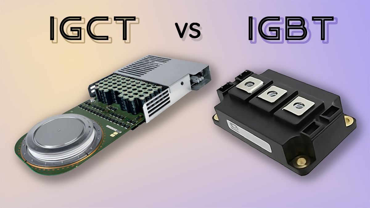
The "Integrated" Edge: This is why it’s called "Integrated". To manage those massive pulses, it comes from the factory with a pre-installed, low-inductance Gate Unit. This drive unit is physically integrated with the device, typically forming a distinctive "hockey puck" or "disk" shape.
Market Dominance: The IGCT sacrifices control flexibility (requiring a bulky and complex drive unit) in exchange for peak efficiency and high-voltage robustness. For 10kV+ applications and multi-megawatt (MW) systems like HVDC or massive mining drives, the IGCT is the undisputed heavy tank of the industry.
Technical Showdown—IGBT vs. IGCT
In the world of power semiconductors, there is no absolute "better" or "worse"—there is only the optimal trade-off for your specific application. To give you a clear picture of how these two heavyweights stack up, let’s look at their core technical specifications side-by-side.

Quick Comparison: Key Technical Parameters
| Feature | IGBT (Insulated Gate Bipolar Transistor) | IGCT (Integrated Gate-Commutated Thyristor) |
|---|
| Control Principle | Voltage Controlled (Gate Voltage) | Current Controlled (Gate Current) |
| Conduction Loss | Higher (due to PN junction drop) | Ultra-Low (Thyristor structure advantage) |
| Max Switching Frequency | High (Typically 1kHz - 20kHz+) | Low (Typically < 1kHz) |
| Gate Drive Circuit | Simple, compact, low power | Complex, bulky, high power (Integrated) |
| Short-Circuit Ruggedness | Strong (Typically 10 microsecond self-limiting) | Weak (Relies on fast fuses or system protection) |
| Typical Voltage Ratings | 600V - 6.5kV | 3.3kV - 10kV+ |
Conduction Loss: The IGCT’s Home Turf
In high-power systems, efficiency is life. Conduction loss is the primary factor determining your cooling system's size and the overall operating cost.
The IGCT Advantage: Because the IGCT is essentially a four-layer thyristor, it benefits from intense conductivity modulation once it's on. This leads to a carrier concentration so high that its on-state voltage drop (V_on) at high currents is significantly lower than a comparable IGBT.
The Formula: Conduction loss can be estimated as: P_cond = V_on × I_load.
The Verdict: For applications handling thousands of amperes, the IGCT drastically reduces heat generation. If your project demands peak efficiency (99% or higher), the IGCT has a natural "home-field" advantage.
Switching Speed & Frequency: The IGBT’s Agility
While conduction loss is one side of the coin, switching loss is the other major expense in AC variable frequency applications.
IGBT: As a non-latching device, it allows for fast charge extraction, with switching times measured in microseconds. This enables stable operation between 1kHz and 20kHz (or even higher). High frequency is a major plus because it allows for smaller, lighter output filters (inductors and capacitors).
IGCT: Even though the integrated gate unit enables "hard-driven" turn-off, the internal carrier recombination process is slower. To prevent the device from overheating, switching frequencies are typically capped between 500Hz and 1kHz.
Engineering Insight: If your motor drive requires high-performance PWM control or minimal output ripple, the IGBT is the more flexible choice.
Gate Drive Complexity: Simple vs. Robust
The gate drive design directly impacts system reliability and the overall physical footprint.
IGBT (Voltage-Driven): The gate acts like a capacitor. You only need to apply a voltage signal (usually +15V/-15V) to control it. The driver circuitry is small, inexpensive, and consumes very little power.
IGCT (Current-Driven): To achieve turn-off, the IGCT gate driver must provide a current pulse that equals or even exceeds the main load current in an incredibly short window.
The Reality: This makes the driver unit massive and complex. This is why the IGCT is always sold as a bundled unit with a large, integrated PCB (the Gate Unit).
Snubber Circuits: Design Simplicity
IGBT: Thanks to its wide Safe Operating Area (SOA), the IGBT can operate "snubberless" in most cases, or with only a small snubber capacitor to suppress voltage spikes.
IGCT: While it is a huge improvement over the older GTO, the IGCT still requires careful design in ultra-high voltage applications. To protect the device from extreme voltage change rates (dv/dt), engineers often must include specific diode and inductor snubber branches, which adds complexity to the system layout.
Applications—Who Rules the Market?
After breaking down the technical specs, the final decision usually comes down to your specific use case. The relationship between the IGBT and IGCT isn't just a simple competition; rather, they have "carved up the territory" based on different power requirements and voltage levels.
The IGBT Stronghold: The Gold Standard for Flexibility
With its compact footprint and superior control characteristics, the IGBT dominates the low-to-medium voltage and segments of the high-voltage market:
EV/HEV Traction Inverters: This is the IGBT’s biggest growth engine. High switching frequencies significantly reduce motor torque ripple and noise, ensuring a smoother and quieter driving experience.
General Purpose Industrial Drives (Low/Medium Voltage): In standard 690V to 3.3kV industrial drives, the IGBT is the undisputed leader due to its simple drive circuitry and ease of maintenance.
Renewable Energy (PV/Wind): Essential for string solar inverters and most onshore wind turbine systems.
Mass Transit and Rail: In subway and light rail traction systems, IGBT modules provide the high power density required for urban mobility.
The IGCT Stronghold: A Symbol of Power and Reliability
As power demands scale from Megawatts (MW) toward the 10MW+ range, the unique advantages of the IGCT become impossible to ignore:
Ultra-High Power MV Drives: In massive applications like mine hoists or steel mill rolling mill drives, the IGCT’s low conduction losses mean a significantly smaller investment in complex cooling systems.
Static Synchronous Compensators (STATCOM): For grid-side applications, the IGCT acts as a "ballast," handling extreme instantaneous power to stabilize grid voltage.
High Voltage Direct Current (HVDC): While many large-scale converter valves now use press-pack IGBTs, the IGCT still holds its ground in specific high-current, low-loss converter stations.
Marine Propulsion Systems: The electric propulsion systems of giant tankers or icebreakers require managing massive power flows within confined spaces—the perfect "sweet spot" for IGCT technology.
Future Trends: The Next Frontier
In today’s power semiconductor market, the rise of SiC (Silicon Carbide) MOSFETs is sparking a technical revolution that is rapidly trickling up from low-voltage sectors into the high-voltage arena. With ultra-fast switching speeds and superior thermal resistance, SiC devices are becoming formidable competitors at the 3.3kV and 6.5kV levels, beginning to eat into the market share traditionally held by IGBTs. For systems prioritizing extreme weight reduction and high-frequency response—such as next-generation high-performance EV traction systems—SiC is quickly becoming the new industry favorite.
However, traditional IGCT technology is far from standing still. Industry leaders like ABB (Hitachi Energy) continue to push the boundaries of IGCT chip design and integrated gate drive solutions. By further slashing conduction losses and enhancing ruggedness, they have ensured that the IGCT remains indispensable in extreme scenarios like offshore wind power, high-power hydrogen electrolysis power supplies, and grid-scale energy conversion. For projects exceeding 10MW that demand a balance of lower upfront capital expenditure (CAPEX) and long-term mission-critical reliability, the IGCT remains the most robust technical choice available today.
Conclusion: Making the Right Choice
When it comes to selecting the right power semiconductor, there is no one-size-fits-all answer. The unique strengths of both the IGBT and IGCT define their specific boundaries within the industrial landscape. To simplify your decision-making process, you can follow these two "Golden Rules" for your next engineering project:
Choose the IGBT if: Your project falls within the low-to-medium power range or requires higher switching frequencies (typically >1kHz) for smoother control. If you prioritize a streamlined design process, compact drive circuitry, and the most mature ecosystem of off-the-shelf components, the IGBT is your best bet.
Choose the IGCT if: Your system is tackling massive power levels (Megawatt-scale and above) and ultra-high voltages where energy conversion efficiency is paramount. In low-frequency environments, the IGCT’s ultra-low conduction losses will save you a fortune in cooling infrastructure and utility costs, making it the "heart" of heavy-duty industrial and grid equipment.