The MRF154 is not just another electronic component; it’s a legend in the world of high-power radio frequency (RF) technology. As a wideband RF power MOSFET designed for linear large-signal output stages, this device has built a lasting reputation for its reliability and performance in the 2.0 to 100 MHz frequency range. While the market has seen a wave of newer technologies, the MRF154 continues to hold an irreplaceable position as a true workhorse in specific applications, thanks to its robust and dependable design.
MRF154 Key Technical Specifications and Performance Metrics
Core Electrical and RF Characteristics
The MRF154 stands out in high-power applications due to its exceptional performance parameters. At its core, it's engineered to deliver a typical output power of 600 watts. When operating at a 50V bias voltage, it achieves a typical power gain of 17 dB and an efficiency of 45% at 30 MHz. Its design for the wide broadband RF range of 2.0 to 100 MHz makes it perfectly suited for a wide variety of high-power linear RF amplifier applications.
Beyond these crucial RF metrics, the device also boasts impressive electrical durability. It features a continuous drain current rating of 60 A and a voltage rating of up to 125 V. With a maximum absolute power dissipation of 1350 W, the MRF154 highlights its immense potential in demanding high-power circuits—a feature that also underscores the critical need for robust thermal management.
The Physics Behind the Performance: TMOS and Parasitic Effects
At its heart, the MRF154 is an N-channel enhancement-mode MOSFET. The physical structure of any MOSFET contains inherent parasitic capacitances between its terminals, and these capacitances are critical to its RF performance. For example, the gate-to-drain capacitance (Cgd) and gate-to-source capacitance (Cgs) originate from the metal-oxide gate structure, while the drain-to-source capacitance (Cds) comes from the PN junction. In the datasheet, these parasitic capacitances are typically characterized as the input capacitance (Ciss), output capacitance (Coss), and reverse transfer capacitance (Crss). These capacitance characteristics directly influence the device's frequency response and impedance matching.
Another key characteristic of this device is its positive temperature coefficient for on-resistance (VDS(on)). This means that as the internal temperature rises, the on-resistance also increases. This phenomenon is a critical factor to consider when designing for high-power, high-temperature applications, as it directly increases power dissipation within the device, placing an even greater demand on the thermal design.
MRF154 Key Specifications at a Glance
| Parameter | Value |
|---|
| Frequency Range | 2.0 to 100 MHz |
| Output Power | 600 W (typical) |
| Power Gain | 17 dB (typical) |
| Efficiency | 45% (typical) |
| Bias Voltage | 50 V |
| Voltage Rating | 125 V |
| Max Drain Current | 60 A (continuous) |
| Max Power Dissipation | 1350 W |
| Technology | N-Channel Enhancement-Mode MOSFET |
| Package | 368-03, Flange Ceramic Pkg |
| Test Voltage/Current | 50 V / 800 mA |
MRF154 Pinout: A Masterclass in High-Power RF Design
The MRF154 features a simple yet elegant pinout, following the classic common source configuration. Its robust CASE 368-03 package, often referred to as the "Hog-Pac," is a flange-mount ceramic package specifically engineered for highly efficient heat dissipation.
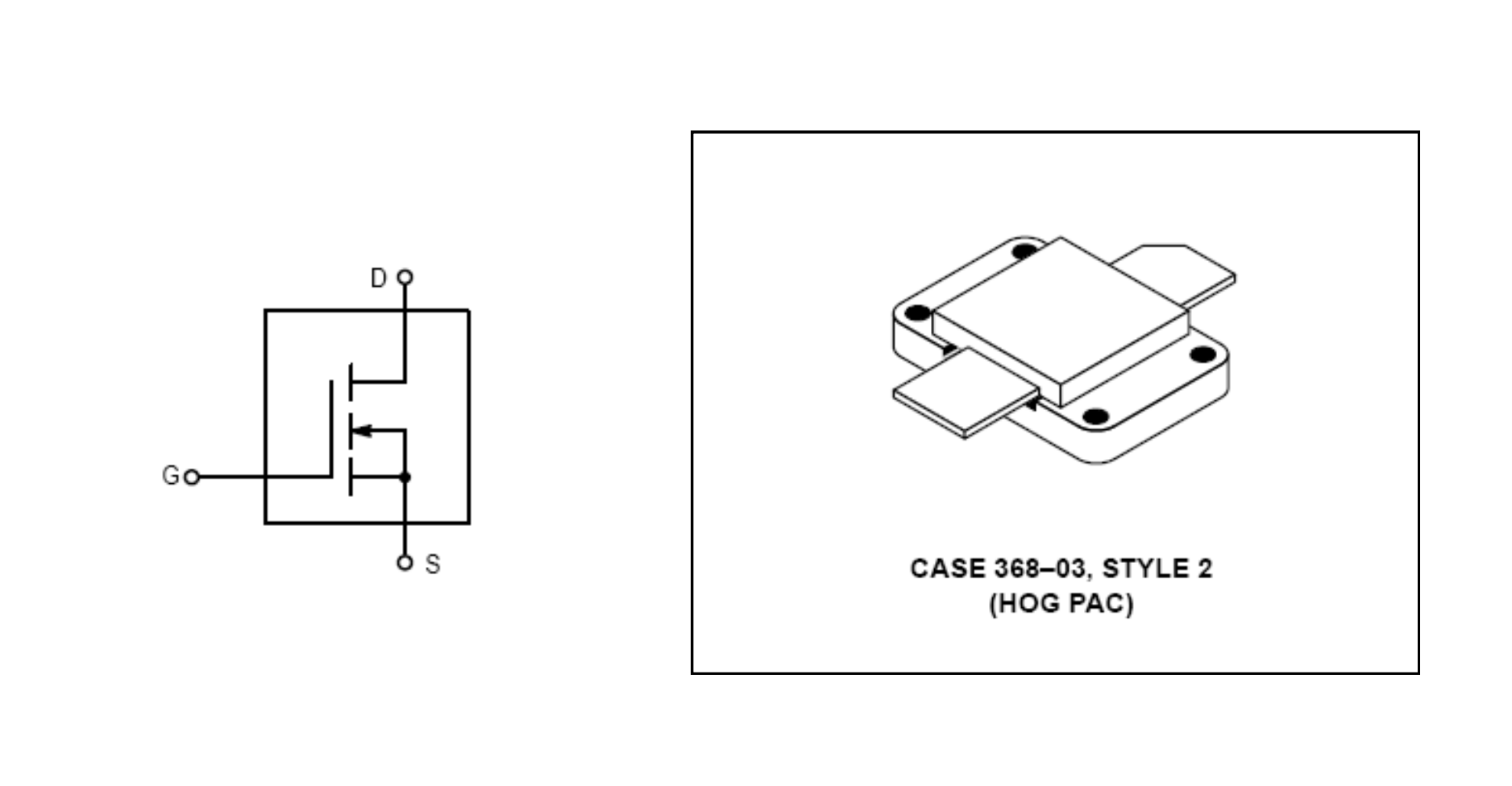
Here is the straightforward pin configuration for this transistor:
Pin 1: Gate
Pin 2: Drain
Flange/Base: Source
In your circuit, the large flange at the base is directly mounted to a heatsink and soldered to the ground plane to serve as the source connection. This design is critical for achieving superior thermal transfer and electrical performance, especially in demanding high-power RF applications.
For successful signal amplification, you simply connect the Gate, Drain, and Flange to their respective parts of the circuit.
The MRF154 Legacy: A Semiconductor Lineage Story
Tracing the Bloodline: From Motorola to MACOM
To truly understand the MRF154's current standing, you have to follow its complex manufacturing history. The device was originally developed by Motorola, with its design credited to applications engineer Helge Granberg. This deep engineering pedigree, born from a company that was a giant in telecommunications, established the MRF154 as a proven and battle-tested design in the industry.

However, a series of mergers and acquisitions in the semiconductor world changed its lineage. Motorola's semiconductor business was spun off into Freescale Semiconductor, which was later acquired by NXP Semiconductors. This complicated chain of events has led some third-party sources to mistakenly list NXP as the manufacturer.
However, official documentation from major distributors and MACOM Technology Solutions (MACOM) clearly identifies MACOM as the current and original manufacturer of the MRF154. This case highlights the importance of carefully tracing a product's history in the complex semiconductor market to find the authoritative source.
The Allure of "New Old Stock" (NOS)
A special term, "New Old Stock" or NOS, plays a significant role in the MRF154 market. NOS refers to products that were manufactured years ago but have remained unsold in pristine, original packaging. The existence of a large NOS market for the MRF154 explains why you might find older versions branded "Motorola" alongside newer versions branded "MACOM."
The thriving NOS market for the MRF154 is a testament to its exceptionally long product lifecycle and enduring reliability. It also points to a consistent and robust demand from niche markets, including amateur radio enthusiasts, repair services, and industrial users needing replacement parts for legacy equipment. Because the supply is limited and prices are determined by the value of the remaining stock, the price of an MRF154 can vary wildly, from a few hundred to over eight hundred dollars, which is a classic characteristic of a highly sought-after legacy component.
VDMOS vs. LDMOS: A Head-to-Head Comparison
As technology has advanced, LDMOS (Laterally Diffused MOSFET) has become the dominant technology for modern high-power RF applications. A direct comparison between the VDMOS technology represented by the MRF154 and LDMOS reveals key design trade-offs.
Performance & Efficiency
Studies show that LDMOS amplifiers generally offer higher gain and efficiency compared to their VDMOS counterparts. This is largely due to the higher source lead inductance of VDMOS, which can reduce power gain. The MRF154’s typical 45% efficiency is a prime example of this, contrasting with the 70% efficiency often seen in LDMOS devices.
Durability & Stability
While LDMOS excels in efficiency, VDMOS holds its own in terms of stability. VDMOS devices like the MRF154 are prized for their superior linearity and resistance to intermodulation distortion, which is essential for linear applications such as single-sideband (SSB) communication. Although LDMOS technology has improved its durability against high VSWR (Voltage Standing Wave Ratio) through complex "drain engineering," the inherent stability of VDMOS remains a compelling advantage. Therefore, the choice between the MRF154 and an LDMOS device is not simply a matter of old versus new; it's a trade-off between maximizing efficiency (LDMOS) and ensuring excellent stability and linearity (VDMOS).
Market Availability & Future Outlook
According to leading distributor platforms, the MRF154 is still listed as an "active" product. However, its long standard production lead time of 36 weeks indicates that new batches are not produced frequently, and supply largely relies on existing inventory. This "active but long lead time" status typically means the device is no longer used for new, high-volume product designs. Instead, it supports existing military, industrial, or communication systems that require replacements for legacy equipment.
The market pricing further confirms this. With prices ranging from a few hundred to over eight hundred dollars, the significant price variance is a classic sign of a legacy component market. The price is driven by the scarcity of remaining stock rather than new production costs. This makes the MRF154 not a general-purpose component for the mass market but a specialized, professional-grade part for specific, critical, or vintage projects.
MRF154 Real-World Applications
The Role of the MRF154 in Linear Amplification
The core design purpose of the MRF154 is its use as a linear large-signal output stage. Linear amplification is critical for applications that demand high-fidelity signal replication, such as single-sideband (SSB) communication, AM broadcasting, and other communication modes where distortion is a concern. In these applications, the RF amplifier must faithfully amplify the input signal without introducing additional harmonics or intermodulation distortion, and the MRF154’s characteristics make it an ideal choice.
Specific Use Cases
The robust performance of the MRF154 has led to its widespread use across several high-power RF fields:
Commercial & Defense: The device is commonly found in broadcast radio and TV, wireless communication systems, and radar systems, particularly within aerospace and defense sectors.
Industrial: In industrial settings, the MRF154 is utilized in equipment requiring high-power RF energy, such as welding devices and plasma generators.
Amateur Radio (Ham Radio): Thanks to its durable design and extensive documentation, the MRF154 is a popular choice for radio amateurs building their own high-power amplifiers. For example, some designs use just two MRF154s to construct a 1200-watt RF amplifier, giving hobbyists a way to achieve high output power with fewer components.
Who Makes the MRF154? A Look at its Manufacturer
The manufacturer of the MRF154 RF power MOSFET is MACOM Technology Solutions, commonly known as MACOM.
MACOM is a company that specializes in designing and producing high-performance analog RF, microwave, millimeter-wave, and photonic semiconductor products. The MRF154 is a classic product in their RF power transistor lineup, primarily used for broadcast, industrial, scientific, and medical (ISM), and other high-power RF applications.
On some older or secondhand products, you might see the manufacturer labeled as "M/A-COM." This is simply the former name of the company that is now MACOM.
Important Considerations When Using the MRF154
Thermal Management: The Critical Challenge
In high-power RF design, thermal management isn’t a secondary concern—it's the primary factor that determines a project's success or failure. The MRF154 is designed for conduction cooling, with its soft copper flange transferring heat directly to a heatsink. To minimize thermal resistance, several key steps must be followed.
First, you must use a main heatsink with a sufficiently low thermal resistance (Rθ). If a copper heatsink isn't used, a copper heat spreader at least 1/4-inch thick is strongly recommended between the device flange and the main heatsink. Second, a thin layer of thermal paste on all contact surfaces is essential. Finally, proper mechanical mounting is crucial. It's recommended to use 4-40 mounting screws tightened to a torque of 4-5 pound-inches, along with spring and flat washers.
These seemingly simple details hide a deep challenge with high-power density devices. As a 600-watt component, the MRF154 concentrates a large amount of heat in a very small area, making effective heat dissipation exceptionally difficult. Unlike using multiple lower-power devices (like the MRF150) to spread the heat, the MRF154 requires a well-designed cooling system. In some cases, air cooling may be insufficient, and liquid cooling solutions may need to be considered.
Biasing, Protection, and Stability
The MRF154’s gate is inherently a capacitor, so when designing your circuit, you must avoid leaving it open or floating. This prevents the device from accidentally turning on due to stray currents or signal pickup. Additionally, never exceed the gate voltage rating, as this can cause permanent damage to the oxide layer.
Because the MRF154 does not include a monolithic Zener diode for protection, it's highly recommended to add an external Zener diode for gate protection if needed. A correctly designed bias circuit is also essential, as it ensures stable operation in specific modes, such as linear amplification.
RF Circuit Layout: Mitigating High-Power Issues
In high-power designs of 500 watts and above, circuit layout becomes critical due to the low impedance levels and associated high RF currents. Here are a few common issues that must be addressed:
Digital/Analog Interference: On the same circuit board, the fast switching of digital signals generates high-frequency components with amplitudes far greater than that of weak RF analog signals. Without physical and electrical isolation, this digital noise can severely interfere with or even destroy the RF signal.
Power Supply Noise: The instantaneous current demands of high-power devices can cause voltage spikes and high-frequency harmonics on the power lines. Therefore, proper power supply decoupling is a must to prevent this noise from reaching the RF circuit's power pins.
Poor Grounding: At RF frequencies, even very short ground wires exhibit inductance. As such, you must use large, continuous ground planes, especially in high-power areas, and avoid using vias whenever possible to ensure your circuit performs as designed.
Conclusion: A Timeless Workhorse in RF Design
The MRF154 wideband RF power MOSFET is a highly influential semiconductor device that represents a significant era in high-power linear amplifier design. While it may not match modern LDMOS technology in terms of sheer efficiency and gain, its superior stability, linearity, and battle-tested design heritage give it an irreplaceable value in specific applications.
MRF154 Frequently Asked Questions (FAQ)
1. What is the MRF154's package, and how does it dissipate heat?
The MRF154 uses a flange-mount ceramic package, often called the "Hog-Pac" or CASE 368-03. Its primary method of heat dissipation is through a large flange at the bottom, which makes direct contact with the circuit board and a large heatsink, efficiently transferring heat away from the device. This is crucial for maintaining stable performance in high-power applications.
2. Is the MRF154 an enhancement-mode or depletion-mode device?
The MRF154 is an enhancement-mode MOSFET. This means it is turned off when there is zero gate-to-source voltage (VGS). To turn it on and begin operation, you must apply a positive VGS voltage.
3. How does the MRF154 differ from the MRF153 or other RF transistors?
The MRF154 is an upgraded version of the MRF153, with the main differences being its power rating and operating frequency range. The MRF154 typically has a higher rated output power (e.g., over 300W at a specific frequency) and optimized gain and efficiency, making it suitable for more demanding, high-power RF amplifier applications. When compared to bipolar junction transistors (BJTs), MOSFETs like the MRF154 generally have a higher input impedance, which simplifies bias circuit design.