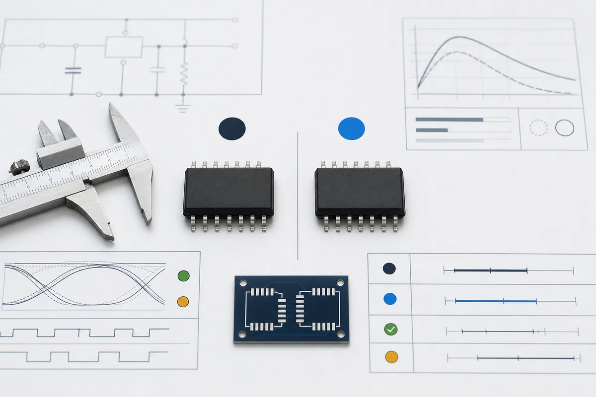
To find an electronic component equivalent safely, start with the exact orderable part number and the requirements of the circuit, not a cross-reference result alone. Treat every suggested alternate as a candidate. Review the applicable manufacturer datasheets and package drawings, then compare pin behavior, electrical limits, timing, thermal performance, software impact, qualification, compliance, and lifecycle.
A search tool can shorten the candidate list. It cannot know every dependency in your board, firmware, production process, or end product. Even a manufacturer-named successor may require component changes, PCB changes, software work, testing, or customer approval.
Procurement can organize the search, but equivalence is an application-specific engineering decision. A controlled review records what must match, what may change, which differences remain open, how the candidate will be validated, and who can approve it. If obsolescence triggered the search, first check the component's lifecycle status for the full manufacturer part number.
This guide is a general review framework. It does not replace part-specific engineering, safety, compliance, quality, or customer approval.
Quick answer: how to find an electronic component equivalent
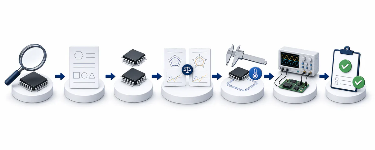
Use this eight-step method:
Confirm the original manufacturer and full orderable part number, including every suffix.
Collect the applicable manufacturer datasheets, ordering table, package drawing, errata, schematic, PCB information, and approved-parts record. Record each document's revision, source, and review date.
Define the required equivalence level. Decide whether the design needs the same function, similar parameters, the same footprint, compatible pins, or a validated drop-in replacement.
List the application limits that must not change, including supply, load, timing, temperature, package, software, qualification, and compliance requirements.
Find candidates through manufacturer product tools, named successors, parametric search, cross-reference tools, approved vendor lists, and sourcing review.
Compare the original and candidate under the same datasheet conditions. Record every difference, missing value, and ambiguous note.
Review package, pinout, thermal path, assembly process, firmware behavior, lifecycle, documentation, and supply risk.
Test representative samples against defined acceptance criteria, obtain the required approvals, and update the BOM, AVL, drawings, software, and inspection plan before release.
Do not approve a candidate because its headline specifications look close. A safe decision needs traceable evidence for the exact orderable variants and the intended application.
Define what equivalent must mean
"Equivalent" is useful only after the team defines the level of compatibility it needs. A part can match one set of parameters and still require a new footprint, different firmware, more cooling, or a fresh product qualification.
| Equivalence level | Practical meaning | What it does not prove |
|---|
| Parametric match | Selected searchable values overlap, such as voltage, value, tolerance, or frequency | Complete electrical behavior, package fit, dynamic performance, or application compatibility |
| Footprint compatible | The candidate may fit the same PCB land pattern | Identical pin functions, body height, exposed-pad connection, electrical behavior, or assembly limits |
| Pin-compatible | Pins in the same positions have compatible functions for the intended design | Equal recommended operating range, startup state, timing, thermal performance, or firmware behavior |
| Functional equivalent | The candidate can perform the required system function after review | No PCB, passive-component, firmware, calibration, or test changes |
| Form-fit-function equivalent | The candidate meets a documented set of mechanical, interface, and functional requirements | Automatic qualification, customer approval, compliance, or supply continuity |
| Drop-in replacement | The candidate can work in a named design without PCB, firmware, or production-process redesign and has passed the required validation | Permission to skip BOM, AVL, ECN, traceability, documentation, or approval controls; universal interchangeability in other designs, environments, revisions, or lots |
These labels answer different questions. A package match does not prove a pinout match. A pinout match does not prove electrical compatibility. A functional match does not prove a drop-in replacement.
Write the required level at the top of the comparison record. If PCB or firmware changes are allowed, say so. If the customer drawing permits only an approved MPN, the commercial search should stay exact-part only until the change process authorizes an alternate.
Start with the original part and the circuit requirement
The search begins with the exact identity of the original part. A shortened family name, top marking, house code, or verbal description is not enough. Confirm the manufacturer and full orderable MPN against manufacturer documentation. Then check the suffixes, package code, temperature or speed grade, qualification option, and packing format.
Build the application baseline before opening a parametric search:
| Requirement area | Evidence to collect |
|---|
| Original identity | Applicable manufacturer datasheet with revision and source, ordering table, package drawing, errata, and applicable PCN or PDN |
| Circuit conditions | Supply tolerance, loads, interfaces, frequency, timing, transients, startup sequence, and protection |
| Mechanical design | PCB land pattern, height limit, orientation, mounting, connector mate, heatsink, airflow, and enclosure clearance |
| Environment | Operating and storage temperature, humidity, vibration, expected life, duty cycle, and failure consequences |
| Product controls | BOM, AVL or AML, schematic, drawing, ECN process, customer approvals, and production test |
| Market requirements | Qualification grade, material declarations, safety approvals, and regulatory evidence for the exact orderable part |
Separate the original part's published features from the design's actual needs. An unused feature does not always need to match. An undocumented dependency in firmware, layout, thermal design, or production test can still block a replacement.
Also record why the team needs an equivalent. The action may differ for a temporary shortage, NRND notice, completed EOL, cost review, performance change, or field repair. If the original is obsolete, compare alternate qualification with the controls required to source obsolete electronic components safely.
Find candidates without treating search results as approval
Use search sources to discover candidates, then keep the technical decision separate.
| Discovery source | Best use | Limitation |
|---|
| Original manufacturer's named successor | Find the manufacturer's intended migration path | The successor may use a different package, pinout, behavior, firmware, or qualification path |
| Manufacturer parametric selector | Filter a current portfolio by published fields | Search fields may omit dynamic, mechanical, software, and application-specific requirements |
| Approved AVL or AML | Start with parts the organization has already considered | Approval may apply only to another product, revision, site, or customer |
| Cross-reference tool | Build a short list across manufacturers | A cross-reference result is not proof of form, fit, function, or drop-in use |
| Sourcing-team or supplier suggestion | Add commercial options and documentation requests | The buyer still needs an engineering and quality review |
For every candidate, record the exact manufacturer, full orderable MPN, discovery source, URL or document, and review date. For an active part, use the current official datasheet and package drawing. For an obsolete part, use a traceable last official or controlled historical revision, along with applicable package drawings, errata, and change notices. Stop the approval if the documents cannot be tied to the exact MPN.
Do not search only by "same or higher" headline ratings. A higher voltage or current rating can come with different capacitance, losses, drive requirements, package construction, or dynamic behavior. Narrow the list with the application baseline, not with one attractive number.
Compare datasheets under the same conditions
Place the applicable original datasheet and current candidate datasheet side by side. Record the comparison in a difference matrix instead of relying on PDF markup and memory.
| Matrix field | What to record |
|---|
| Requirement | The circuit or product limit the candidate must meet |
| Original value | Specified original-part min/max value, exact document revision, and test conditions |
| Candidate value | Specified candidate min/max value under comparable conditions and from the exact document revision |
| Difference | Numerical, behavioral, package, documentation, or unknown difference |
| Risk | How the difference could affect function, margin, reliability, production, or approval |
| Evidence | Datasheet table, graph, note, package drawing, errata, or test record, with document revision, source, and review date |
| Owner and action | Person responsible for analysis, test, supplier question, or approval |
Compare more than nominal function. Depending on the part, the review may include:
Recommended supply range, tolerances, ripple, sequencing, inrush, quiescent current, and shutdown current.
Input and output thresholds, leakage, drive strength, pull resistors, output type, and powered-off behavior.
Accuracy, offset, noise, bandwidth, stability, load response, common-mode range, and reference behavior.
Setup and hold time, propagation delay, pulse width, rise and fall time, jitter, skew, wake-up time, and fault recovery.
Conduction and switching losses, gate charge, safe operating area, reverse-recovery behavior, transient response, and protection needs.
Use recommended operating conditions, not absolute maximum ratings
Absolute maximum ratings define stress limits. They are not normal operating points, and operation near those limits may not carry functional or reliability guarantees. Define normal limits from the recommended operating conditions, then include tolerance, transient, temperature, and derating margin.
An equal or higher absolute maximum rating does not prove equivalence. The candidate still needs to meet the specified min/max electrical limits in the actual operating region.
Compare like with like
Check the units, temperature, supply voltage, load, frequency, and measurement method behind every value. Do not compare a candidate's typical value with an original part's specified maximum and call the candidate better. A missing limit is an open question, not a pass.
Datasheet conventions differ. Treat a min/max value as a specified limit only within its stated notes and test conditions, and call it guaranteed only when the manufacturer says so. Graphs and application notes can explain behavior, but they may show typical characterization rather than production-tested limits. Keep specified limits, typical behavior, and application assumptions separate in the matrix.
Check package, pinout, thermal, and assembly fit
The same package family or pin count does not prove physical compatibility. Compare the exact manufacturer drawings and ordering codes.
Check:
Body dimensions, tolerances, height, pitch, lead style, coplanarity, mounting holes, and terminal positions.
Recommended land pattern, pad geometry, solder-mask guidance, pin 1 orientation, polarity, and keep-out areas.
Every power, ground, signal, enable, sense, no-connect, do-not-connect, reserved, and exposed-pad function.
Lead finish, moisture sensitivity level, peak reflow limits, cleaning restrictions, tray or reel orientation, and placement requirements.
Creepage, clearance, isolation construction, connector keying, mating part, plating, and insertion-cycle requirements where relevant.
Thermal data also needs context. Junction-to-ambient thermal resistance can depend heavily on the test board, copper area, airflow, and package. Do not compare values from different test setups and conclude that one part runs cooler.
Estimate loss at the real operating point and review junction, case, and ambient limits. Check exposed pads, heatsinks, baseplates, interface materials, mounting torque, transient thermal impedance, and cooling conditions as applicable. A candidate that fits the footprint can still exceed the thermal budget.
Review system behavior, compliance, and lifecycle
Headline electrical tables do not cover every replacement risk. Add these checks before the candidate reaches sample approval.
| Review area | What may differ | What to verify |
|---|
| Startup and fault behavior | Reset state, power sequencing, brownout response, enable timing, protection, and recovery | Circuit behavior at power-up, shutdown, transient, and fault conditions |
| Firmware and digital interface | Register map, address, device ID, defaults, reserved bits, commands, interrupts, driver, and silicon errata | Required code changes, programming flow, diagnostics, and regression tests |
| Qualification and reliability | Temperature grade, mission profile, automotive or other qualification, assembly site, die revision, and reliability evidence | Manufacturer documentation for the exact orderable part and any product or customer approval |
| Material and regulatory status | RoHS, REACH, lead finish, flammability, safety isolation, export, or customer declarations | Current documents for the exact part, package, revision, and target market |
| Lifecycle and change control | Active, NRND, EOL, obsolete, PCN, PDN, or a planned process change | Current manufacturer page, affected ordering code, notice date, and internal ECN impact |
| Commercial and quality controls | Source, traceability, date code, packaging, storage, inspection, and sample availability | RFQ-specific evidence and buyer-defined acceptance requirements |
A technically promising candidate can be a poor choice if it is already NRND or nearing EOL. Manufacturers use their own lifecycle terms, so consult official sources such as the TI product lifecycle definitions and the NXP product lifecycle definitions.
Review notices as part of change control. TI's product change notification guidance is one manufacturer example; the applicable notice and terminology depend on the candidate's manufacturer.
Incoming inspection, documentation, or X-ray review may reveal anomalies and support an identity or condition investigation. Select the inspection scope for the component type, source risk, application consequences, and buyer requirements. No single inspection method proves authenticity, traceability, or circuit equivalence by itself. Keep sourcing quality evidence and design-equivalence evidence as separate approval records.
Use the right checkpoints for each component type
An op amp, power module, capacitor, and connector need different evidence. Use the table as a starting point, then add the requirements of the actual circuit.
| Component type | Check beyond basic function and package |
|---|
| Analog and interface ICs | Input and output range, offset, bias, noise, bandwidth, stability, load drive, common-mode behavior, logic thresholds, protection, and powered-off I/O state |
| Microcontrollers, memory, and digital ICs | Architecture, memory organization, speed grade, voltage, timing, pin multiplexing, boot mode, register map, programming method, endurance, data retention, security features, toolchain, firmware, and errata |
| MOSFETs, IGBTs, diodes, and power modules | Voltage and current at the required conditions, conduction loss, switching loss, gate charge and drive, safe operating area, reverse recovery, avalanche or short-circuit behavior where specified, isolation, thermal path, and terminal layout |
| Resistors | Resistance, tolerance, temperature coefficient, rated power with derating, working voltage, pulse or surge capability, package construction, and long-term stability |
| Capacitors | Capacitance under DC bias and temperature, tolerance, dielectric, voltage rating, ESR, ESL, ripple current, leakage, aging, polarity, package, and failure mode |
| Inductors and transformers | Inductance at the stated frequency, tolerance, saturation current, temperature-rise current, DCR, self-resonant frequency, core loss, isolation, winding, and footprint |
| Connectors and relays | Pitch, mating part, keying, contact layout, plating, current and voltage rating, insertion life, coil data, contact form, switching load, isolation, mounting, and agency requirements |
| Crystals and oscillators | Frequency, tolerance, stability, load capacitance, ESR, drive level, startup time, output format, phase noise or jitter, supply, package, and temperature range |
Headline ratings can hide tradeoffs. A power transistor with a higher voltage rating may have different losses or gate-drive needs. A capacitor with the same printed capacitance may deliver less effective capacitance under DC bias. A connector with the same pitch may use different keying or plating.
For a mixed BOM, record whether each line is exact-only, already approved, or still a candidate. That distinction makes it easier to review alternates across the BOM without letting an unapproved suggestion enter purchasing data.
Worked IGBT/IPM example: PM50RL1A120 vs PM75RL1A120
The part number can shortlist this pair, but it cannot approve the substitution. PM50RL1A120 and PM75RL1A120 are Mitsubishi Electric intelligent power modules (IPMs), not bare IGBTs. Each module combines a three-phase IGBT inverter, a brake circuit, gate drive, and protection functions.
Mitsubishi Electric's L1/S1-series application note, page 10, decodes the model names:
| Model field | Meaning in this series | PM50RL1A120 | PM75RL1A120 |
|---|
PM | Intelligent power module | Match | Match |
50 / 75 | Inverter collector-current rating | 50 A | 75 A |
R | 7-pack connection: inverter plus brake | Match | Match |
L1A | L1-series package with screw-type main terminals | Match | Match |
120 | 1200 V voltage class | Match | Match |
The matching PM, R, L1A, and 120 fields identify the same module family, connection, main-terminal style, and voltage class. The current field is different. It is a rating, not a revision code. The model-number verdict is narrow: PM75RL1A120 is a higher-current same-family candidate for engineering review, not an approved direct replacement.
What the official documents confirm
Mitsubishi Electric's current product pages list both PM50RL1A120 and PM75RL1A120 as discontinued L1-series 7-pack IPMs. Their exact May 2009 PM50RL1A120 datasheet and PM75RL1A120 datasheet show where the match ends:
| Comparison point | PM50RL1A120 | PM75RL1A120 | Screening result |
|---|
| Inverter collector-emitter voltage, maximum rating | 1200 V | 1200 V | Headline match |
| Inverter collector current / peak collector current, maximum ratings at Tc = 25 °C | 50 A / 100 A | 75 A / 150 A | Different |
| Brake collector current / peak collector current, maximum ratings at Tc = 25 °C | 25 A / 50 A | 50 A / 100 A | Different |
| Collector dissipation, maximum ratings at Tc = 25 °C, inverter / brake | 462 W / 320 W | 595 W / 462 W | Different maximum dissipation ratings; not an operating-loss comparison |
| Connection / isolation-voltage rating | 7-pack / 2500 Vrms | 7-pack / 2500 Vrms | Headline match |
| Published external outline and terminal assignment | Same arrangement shown | Same arrangement shown | Promising physical-fit evidence, not final approval |
| Short-circuit trip level, minimum, inverter / brake | 100 A / 50 A | 150 A / 100 A | Different protection thresholds |
| Junction-to-case thermal resistance, maximum, inverter IGBT | 0.27 °C/W | 0.21 °C/W | Different thermal characteristic |
| Current product-page status | Discontinued | Discontinued | No lifecycle-continuity advantage |
The published outline and terminal arrangement support the physical-fit screen: PM50RL1A120 and PM75RL1A120 use the same L1-series 7-pack, 1200 V, screw-terminal IPM package. The main difference is rating level. PM75RL1A120 is the higher-current version, with higher inverter and brake current ratings, higher short-circuit trip levels, and different thermal and dissipation limits.
For equipment originally designed around PM50RL1A120, PM75RL1A120 can be used as an upward replacement when the operating conditions remain within the PM75RL1A120 datasheet limits and the control, mounting, cooling, and protection design are compatible. Under the same PM50 application load, the PM75 module provides more rating headroom, which can be valuable in higher-load, higher-temperature, or more demanding operating environments.
The trade-off is cost. PM75RL1A120 is a higher-rated module and is typically more expensive than PM50RL1A120, so the substitution may increase repair or production cost. If the original PM50RL1A120 already meets the application’s current, temperature, and reliability requirements, PM75RL1A120 may be an over-specified replacement. But where additional safety margin is desired and the higher cost is acceptable, PM75RL1A120 is a valid higher-capacity substitute for PM50RL1A120. This conclusion is one-way: PM50RL1A120 should not be used to replace PM75RL1A120 in equipment that requires the PM75 rating.
Worked IC replacement example: LM358DR vs LM358BIDR
Texas Instruments identifies LM358B as a drop-in replacement with upgraded functionality for LM358 at the product-family level. For a BOM that specifies an SOIC-8 device on a large tape-and-reel, the exact orderable pair to compare is LM358DR and LM358BIDR. LM358BIDR matches LM358DR's package and carrier, so it aligns with TI's family-level forward-upgrade statement. The two cited TI sources do not separately state application-specific approval for this exact BOM change. The two ICs are not electrically identical or bidirectional replacements.
Read the complete orderable part numbers
The shared LM358 identifies the dual operational-amplifier family. The remaining characters matter because they select the version, temperature range, package, and carrier for these specific TI orderables:
| Order-code field | LM358DR | LM358BIDR | What it tells the reviewer |
|---|
| Base device | LM358 | LM358 | Same basic dual-op-amp function |
| Device version | Original version | B next-generation version | Performance is upgraded, not identical |
| Listed operating temperature | 0 °C to 70 °C | I: -40 °C to 85 °C | The B orderable covers a wider range |
| Package | D: 8-pin SOIC | D: 8-pin SOIC | Package code and pin count match |
| Carrier | R: 2,500-piece large tape-and-reel | R: 2,500-piece large tape-and-reel | Assembly supply format matches |
Do not apply those suffix meanings to another manufacturer without checking its naming rules. The evidence here comes from TI's records for these exact orderable part numbers.
What the current TI data confirms
TI's current LM358 family datasheet gives the pinout, electrical tables, and package addendum for both devices. The values below are each device's published specifications under its own table conditions, not results from one controlled head-to-head test or a complete qualification:
| Comparison point | LM358DR | LM358BIDR | Replacement implication |
|---|
| Status / material type | Active / Production | Active / Production | Both exact codes are current in the reviewed package addendum |
| Function and SOIC-8 pinout | Dual op amp; standard 8-pin assignment | Same | Supports pin-to-pin screening |
| Recommended supply range | 3 V to 30 V | 3 V to 36 V | B covers the original range and extends it |
| Operating temperature for these orderables | 0 °C to 70 °C | -40 °C to 85 °C | B covers the original listed range |
| Published input offset magnitude at 25 °C | 3 mV typical, 7 mV maximum | 0.3 mV typical, 3 mV maximum | B improves precision, but a changed offset can still affect thresholds or calibration |
| Gain-bandwidth product | 0.7 MHz typical | 1.2 MHz typical | Closed-loop response and stability still need review |
| Slew rate at gain of 1 | 0.3 V/μs typical | 0.5 V/μs typical | Transient behavior is not identical |
| RF and EMI input filtering | Not a listed original-version feature | Integrated filter | High-frequency behavior can change |
The pin configuration appears on datasheet page 3, recommended operating ranges on page 5, and the two electrical tables on pages 6 and 10. The package addendum, PDF page 39 and Addendum Page 7, is dated July 15, 2026. It lists both exact orderables as Active / Production, 8-pin SOIC (D), 2,500-piece large tape-and-reel, RoHS, and MSL Level 1. It lists LM358DR for 0 °C to 70 °C and LM358BIDR for -40 °C to 85 °C. These details confirm a close BOM and assembly match. They do not replace circuit review.
For the forward change, compare the input common-mode range, output swing and load, bias current, noise, open-loop behavior, capacitive load, overload recovery, and startup behavior under the real supply and temperature conditions. Check whether the higher bandwidth and slew rate alter overshoot, oscillation margin, filtering, or settling. Revalidate any threshold, gain-error, or calibrated function that depends on input offset. Review customer, regulatory, quality, and change-control requirements before release.
Classify LM358BIDR as a forward candidate supported by TI's family-level drop-in and pin-to-pin upgrade statement. Engineering approval still requires circuit-level validation and a documented change record. The reverse direction, LM358BIDR to LM358DR, is not automatic: it can fail if the design uses more than 30 V, operates below 0 °C or above 70 °C, or depends on the B version's precision, speed, filtering, or other limits.
Validate the candidate and control approval
Datasheet comparison reduces the risk, but it does not reproduce the complete application. Build a validation plan around the product's failure consequences and the differences found in the matrix.
Scale validation to the product risk. The process may include:
Assign an owner to every difference, missing specification, and supplier question.
Obtain representative samples tied to the exact orderable MPN and available documentation.
Confirm identity, package, condition, labeling, and handling before electrical evaluation.
Run board-level A/B tests across the required supply, temperature, load, frequency, and tolerance corners.
Check startup, shutdown, brownout, transients, faults, protection, recovery, and any operating modes that production test does not cover.
Measure the performance that matters to the design, such as accuracy, timing, loss, temperature, signal integrity, noise, or EMI behavior.
Run firmware, programming, diagnostics, calibration, and system regression tests where applicable.
Complete any environmental, reliability, safety, regulatory, customer, or production qualification required by the product.
Use a pilot build or risk-based sample plan with acceptance criteria defined before the results are reviewed.
Record approval and update controlled BOMs, AVL records, drawings, ECNs, software, test limits, and incoming-inspection instructions.
One room-temperature power-on test shows only that the tested sample worked under that condition. It does not prove equivalent behavior across voltage, temperature, load, process variation, service life, or other lots.
Engineering should approve functional and design compatibility. Quality should review inspection, reliability, and change-control needs. Firmware, regulatory, manufacturing, or the customer may also need to approve the change. Define those owners before samples arrive.
NTCHIP's quality control page can support a discussion about inspection and verification requirements, but the buyer should set the application-specific validation scope and acceptance criteria.
Know when not to substitute
Stop the alternate review when a critical unknown cannot be resolved. Typical stop conditions include:
The full original or candidate orderable MPN, applicable current or traceable last official datasheet, or package drawing cannot be confirmed.
Recommended operating limits, pin functions, exposed-pad connections, timing, thermal design, or fault behavior have an unresolved difference.
The change needs PCB or firmware work but has no owner, schedule, or validation plan.
Safety, regulatory, qualification, traceability, or customer approval evidence is missing.
The candidate's lifecycle or source cannot support the product requirement.
The team cannot test a difference that could create an unacceptable failure.
The only support for release is a cross-reference table, a verbal sales claim, or one uncontrolled sample test.
The better decision may be to keep sourcing the exact part, redesign the affected circuit, or change the product plan. For obsolete requirements, compare the cost and risk of exact-part sourcing, a controlled lifetime purchase, alternate qualification, and redesign. Do not force a substitution simply because a candidate is easier to quote.
Prepare an alternate-component RFQ
An RFQ that says only "or equivalent" leaves the sourcing team to guess what can change. State the technical and approval limits before asking for alternatives.
| RFQ field | What to provide |
|---|
| Original part | Manufacturer and full orderable MPN, including suffixes |
| Requirement type | Exact-only, approved alternates allowed, or new candidate review requested |
| Candidate parts | Full candidate MPNs already under review, if any |
| Quantity and timing | Required quantity, target date, production or repair context, and expected follow-on demand |
| Application context | Product type, circuit function, operating environment, and risk level that can be shared |
| Must-match requirements | Electrical, timing, package, pinout, thermal, software, qualification, compliance, and lifecycle limits |
| Permitted changes | Whether PCB, passive, firmware, test, labeling, or documentation changes are allowed |
| Evidence requested | Datasheet, package drawing, lifecycle status, PCN or PDN, material declarations, traceability, and other required documents |
| Quality requirements | Date-code limits, packaging, storage, sample, inspection, test, or reporting needs |
| Approval path | Engineering, quality, customer, or regulatory approvals still required |
Ask the sourcing team to identify each response as:
That distinction prevents a quoted candidate from being mistaken for an approved substitute. Use the NTCHIP request a quote form to send the original MPN, quantity, target date, alternate policy, and available technical requirements. Availability, pricing, lead time, documentation, and inspection scope should be confirmed for the specific RFQ.
How NTCHIP can support an equivalent-part request
NTCHIP can help buyers organize sourcing options for exact, obsolete, hard-to-find, or alternate electronic components. Start the request with the original manufacturer and full MPN, quantity, target date, and acceptable-alternate status. Add datasheets, package needs, application constraints that can be shared, and any documentation or inspection requirements.
NTCHIP can communicate candidate and sourcing information for review. Final replacement approval should follow the buyer's engineering, quality, firmware, manufacturing, regulatory, and customer processes. No candidate should be treated as compatible until the required evidence and validation are complete.
Frequently asked questions
What makes two electronic components equivalent?
They are equivalent only when the candidate meets the requirements defined for a specific application and has passed the required review and validation. Matching a few catalog parameters is not enough.
Is a cross-reference part a drop-in replacement?
Not automatically. A cross-reference tool finds candidates. Verify the exact MPN, applicable datasheets, electrical limits, test conditions, package, pin behavior, thermal performance, firmware impact, qualification, compliance, lifecycle, and application test results before calling a part drop-in.
Can two parts with the same package be interchangeable?
The package name and pin count can match while the land pattern, body tolerances, pin functions, exposed pad, orientation, thermal performance, or assembly limits differ. Compare the exact package drawings and every connected pin.
Does a higher voltage or current rating make a candidate safer?
No. A higher headline rating may add margin for one stress, but the candidate can have different losses, capacitance, gate drive, timing, protection, safe operating area, or thermal behavior. Compare the complete operating requirements.
Can PM75RL1A120 replace PM50RL1A120?
The model number and Mitsubishi Electric documents support treating PM75RL1A120 as a higher-current same-family candidate. They do not establish a direct replacement. The published outline, terminal arrangement, voltage class, and connection match, but inverter and brake ratings, protection thresholds, and thermal characteristics differ. Compare both exact datasheets under the PM50 application conditions, then validate the module in the target equipment before approval. This does not make PM50RL1A120 a candidate for an application that requires the PM75 ratings.
Can LM358BIDR replace LM358DR?
TI identifies LM358B as a drop-in, pin-to-pin upgrade for LM358 at the product-family level. LM358DR and LM358BIDR share the 8-pin SOIC package and reel format, so the exact pair aligns with that forward upgrade statement. The two cited TI sources do not separately state application-specific approval for this exact BOM change. Validate stability, input and output limits, loading, calibration, and change-control requirements. Do not assume the reverse direction: LM358DR may not cover a design that uses the B version above 30 V, outside 0 °C to 70 °C, or for its improved performance.
Who should approve an alternate electronic component?
Procurement or a supplier can propose candidates. The buyer's engineering function should approve design compatibility, with quality, firmware, manufacturing, regulatory, or customer approval added when the product requires it.
Can an obsolete component be replaced without redesigning the board?
Sometimes, but only if a candidate meets the defined drop-in requirements and passes the required validation. If package, pinout, electrical behavior, firmware, or qualification differs, the change may need a board, BOM, software, test, or product-approval update.
Does incoming inspection prove that a candidate is equivalent?
No. Incoming inspection may reveal anomalies in identity, packaging, condition, documentation, or selected quality attributes. It cannot by itself prove authenticity, traceability, or equivalence. Equivalence also requires design comparison and application validation.
What information helps an equivalent-part RFQ?
Send the original manufacturer and full MPN, quantity, target date, application constraints, must-match specifications, permitted changes, candidate MPNs, qualification and compliance needs, documentation requests, inspection requirements, and approval status.
Treat equivalence as an approval decision
A similar part number or cross-reference hit starts the search. It does not finish the approval. Confirm the exact original part, define what must match, compare the applicable datasheets under the same conditions, review physical and system-level differences, and validate the candidate against written acceptance criteria.
Keep every unknown visible in the comparison record. Assign it to an owner, resolve it with evidence or testing, and update controlled product records after approval.
For a sourcing review, send NTCHIP the original MPN, quantity, target date, alternate policy, candidate list, and quality requirements. Commercial details and available sourcing options can then be reviewed without confusing a proposed candidate with an approved replacement.